
PartB:
2.Interface and Control a DC Motor.
Theory:
A DC motor is any of a class of rotary electrical machines that converts direct current electrical energy into mechanical energy. The most common types rely on the forces produced by magnetic fields. Nearly all types of DC motors have some internal mechanism, either electromechanical or electronic, to periodically change the direction of current flow in part of the motor.
Block Diagram

case1:
 case2:


#include <LPC17xx.H>
void Clock_Wise(void);
void AClock_Wise(void);
unsigned long i;
int main(void)
{
SystemInit();
LPC_PINCON->PINSEL1 &= 0xFFCFFFFF; //P0.26 GPIO, P0.26 controls dir
LPC_PINCON->PINSEL3 &= 0xFFFCFFFF; //P1.24 GPIO
LPC_GPIO0->FIODIR |= 0x04000000; //P0.26 output
LPC_GPIO1->FIODIR |= 0x01000000; //P1.24 output
while(1)
{
Clock_Wise();
for(i=0;i<200000;i++);
AClock_Wise();
for(i=0;i<200000;i++);
} //end while(1)
} //end main
void Clock_Wise(void)
{
LPC_GPIO1->FIOCLR = 0x01000000; //P1.24 Kept low to off DCM
for(i=0;i<10000;i++); //delay to componsate inertia
LPC_GPIO0->FIOSET = 0x04000000; //P0.26 coil is on
LPC_GPIO1->FIOSET = 0x01000000; //P1.24 motor in on
return;
} //end void Clock_Wise(void)
void AClock_Wise(void)
{
LPC_GPIO1->FIOCLR = 0x01000000; //P1.24 Kept low to off DCM
for(i=0;i<10000;i++); //delay to componsate inertia
LPC_GPIO0->FIOCLR = 0x04000000; //P0.26 coil is off
LPC_GPIO1->FIOSET = 0x01000000; //P1.24 Motor is on
return;
} //end void AClock_Wise(void)
*********************************************************************************
//DC motor clockwise direction rotation based on push botton status
#include<LPC17xx.h>
void Clock_Wise(void);
void AClock_Wise(void);
unsigned long i;
unsigned int key;
int n=100000;
int j;
int main(void)
{
SystemInit();
LPC_PINCON->PINSEL1 &=0xFFCFFFFF;
LPC_PINCON->PINSEL3 &=0xFFFFCFFF;
LPC_PINCON->PINSEL4 &=0x00000000;
LPC_GPIO0->FIODIR|=0x04000000;//GPIO functionality selection of Port 0
LPC_GPIO1->FIODIR|=0x01000000;//GPIO functionality selection of Port 1
LPC_GPIO2->FIODIR |=0x00000000;//GPIO functionality selection of Port 2
while(1)
{
key=LPC_GPIO2->FIOPIN;
key=key&0x00000800;
if(key==0x00000800)
{
LPC_GPIO1->FIOCLR=0x01000000;
}
else
{
Clock_Wise();
for(i=0;i<200000;i++);
}
}
}
void Clock_Wise(void)
{
LPC_GPIO1->FIOCLR=0x01000000;
for(i=0;i<10000;i++);
LPC_GPIO0->FIOSET=0x040000000;
LPC_GPIO1->FIOSET=0X01000000;
}
*********************************************************************************
control speed of DC motor using PWM

Explanation:
Download:control DC motor
2.Interface and Control a DC Motor.
Theory:
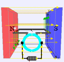
Stationary permanent magnets form the stator field. Torque is produced by the principle that any current-carrying conductor placed within an external magnetic field experiences a force, known as Lorentz force. In a motor, the magnitude of this Lorentz force (a vector represented by the green arrow), and thus the output torque,is a function for rotor angle, leading to a phenomenon known as torque ripple) Since this is a two-pole motor, the commutator consists of a split ring, so that the current reverses each half turn ( 180 degrees).
DC motors were the first type widely used, since they could be powered from existing direct-current lighting power distribution systems. A DC motor's speed can be controlled over a wide range, using either a variable supply voltage or by changing the strength of current in its field windings. Small DC motors are used in tools, toys, and appliances.
DC motorBlock Diagram

case1:


fig: relay working

fig: phase reversal property of CE configuration

fig: darlington emitter pair used to get high current gain (beta parameter)
#include <LPC17xx.H>
void Clock_Wise(void);
void AClock_Wise(void);
unsigned long i;
int main(void)
{
SystemInit();
LPC_PINCON->PINSEL1 &= 0xFFCFFFFF; //P0.26 GPIO, P0.26 controls dir
LPC_PINCON->PINSEL3 &= 0xFFFCFFFF; //P1.24 GPIO
LPC_GPIO0->FIODIR |= 0x04000000; //P0.26 output
LPC_GPIO1->FIODIR |= 0x01000000; //P1.24 output
while(1)
{
Clock_Wise();
for(i=0;i<200000;i++);
AClock_Wise();
for(i=0;i<200000;i++);
} //end while(1)
} //end main
void Clock_Wise(void)
{
LPC_GPIO1->FIOCLR = 0x01000000; //P1.24 Kept low to off DCM
for(i=0;i<10000;i++); //delay to componsate inertia
LPC_GPIO0->FIOSET = 0x04000000; //P0.26 coil is on
LPC_GPIO1->FIOSET = 0x01000000; //P1.24 motor in on
return;
} //end void Clock_Wise(void)
void AClock_Wise(void)
{
LPC_GPIO1->FIOCLR = 0x01000000; //P1.24 Kept low to off DCM
for(i=0;i<10000;i++); //delay to componsate inertia
LPC_GPIO0->FIOCLR = 0x04000000; //P0.26 coil is off
LPC_GPIO1->FIOSET = 0x01000000; //P1.24 Motor is on
return;
} //end void AClock_Wise(void)
*********************************************************************************
//DC motor clockwise direction rotation based on push botton status
#include<LPC17xx.h>
void Clock_Wise(void);
void AClock_Wise(void);
unsigned long i;
unsigned int key;
int n=100000;
int j;
int main(void)
{
SystemInit();
LPC_PINCON->PINSEL1 &=0xFFCFFFFF;
LPC_PINCON->PINSEL3 &=0xFFFFCFFF;
LPC_PINCON->PINSEL4 &=0x00000000;
LPC_GPIO0->FIODIR|=0x04000000;//GPIO functionality selection of Port 0
LPC_GPIO1->FIODIR|=0x01000000;//GPIO functionality selection of Port 1
LPC_GPIO2->FIODIR |=0x00000000;//GPIO functionality selection of Port 2
while(1)
{
key=LPC_GPIO2->FIOPIN;
key=key&0x00000800;
if(key==0x00000800)
{
LPC_GPIO1->FIOCLR=0x01000000;
}
else
{
Clock_Wise();
for(i=0;i<200000;i++);
}
}
}
void Clock_Wise(void)
{
LPC_GPIO1->FIOCLR=0x01000000;
for(i=0;i<10000;i++);
LPC_GPIO0->FIOSET=0x040000000;
LPC_GPIO1->FIOSET=0X01000000;
}
*********************************************************************************
control speed of DC motor using PWM

#include <lpc17xx.h>
void pwm_init(void);
void PWM1_IRQHandler(void);
unsigned long int i,j;
unsigned char flag,flag1;
int main(void)
{
SystemInit();
SystemCoreClockUpdate();
pwm_init();
while(1)
{
for(i=0;i<=1000;i++); // delay
}
} //end of main
void pwm_init(void)
{
LPC_SC->PCONP |= (1<<6); //PWM1 is powered
LPC_PINCON->PINSEL3 |= 0x00020000; //pwm1.5 is selected for the pin P1.24
LPC_PWM1->PR = 0x00000000; //Count frequency : Fpclk
LPC_PWM1->PCR = 0x00002000; //select PWM5 single edge and PWM5 output is enabled
LPC_PWM1->MCR = 0x00000003; //Reset and interrupt on PWMMR0
LPC_PWM1->MR0 = 0X00007530; //setup match register 0[MR0] count to cycle time
LPC_PWM1->MR5 = 0x00000064; //setup match register 5[MR5] coount to duty cycle
LPC_PWM1->LER = 0x000000FF; //enable shadow copy register
LPC_PWM1->TCR = 0x00000002; //RESET COUNTER AND PRESCALER
LPC_PWM1->TCR = 0x00000009; //enable PWM and counter
NVIC_EnableIRQ(PWM1_IRQn);
return;
}
void PWM1_IRQHandler(void)
{
LPC_PWM1->IR = 0xff; //clear the interrupts
if(flag == 0x00) // to increase the Ton period by 64 for every iteration till MR5 is less than 6978
{
LPC_PWM1->MR5 += 0X00000064;
LPC_PWM1->LER = 0x000000FF;
if(LPC_PWM1->MR5 >= 0X00006978)
{
flag1 = 0xff;
flag = 0xff;
LPC_PWM1->LER = 0x000000FF;
}
for(i=0;i<8000;i++);
}
else if(flag1 == 0xff) // to increase the Toff period or to decrease Ton period by 64 for every iteration till MR5 is greater than BB8
{
LPC_PWM1->MR5 -= 0X00000064;
LPC_PWM1->LER = 0x000000FF;
if(LPC_PWM1->MR5 <= 0x00000BB8)
{
flag = 0x00;
flag1 = 0x00;
LPC_PWM1->LER = 0X000000FF;
}
for(i=0;i<8000;i++);
}
}
Download:control DC motor
No comments:
Post a Comment